Contents
Trigonometric identites Frequently used in complex power calculations
|
Signal |
Instantaneous Power
|
|
|
|
|
|
|
|
|
|
|
Average , Maximum and Minimum power in terms of power factor (PF) |
|
|
|
Complex Power |
|
1. Apparent Power is the magnitude of the complex power.
2. Average/Real Power and Reactive Power is the real part and imaginary part of the complex power respectively.
3. Unit of reactive power is VARS |
|
Reactive Power (VARS) |
|
|
|
Average Power/Real Power
|
|
|
|
Complex Power |
|
1.
Apparent Power =
2. The unit of apparent power is VA
3. Apparent power is the magnitude of the complex power. |
|
|
1.
Complex Power 2.
Real Power 3.
Reactive Power 4.
Apparent Power |
|
|
|
|
|
|
|

|
|
|
|
|
|
|
Average value of |
|
|
Average value of |
|
|
|
|
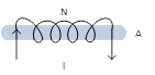
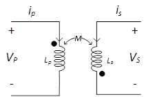
Inductance of a coil with N turns,
cross section area A, length L and core permeability |
|
|
|
Voltage induced across an inductor |
|
|
|
Voltage induced across a coil (w.r.t
flux linkage |
|
|
|
Flux linkage |
|
|
|
Energy stored in an inductor |
|
|
|
Magnetic equivalent of electric current |
Source of EMF is battery |
Source of MMF is current coil |
|
|
|
|
|
|
|
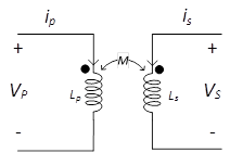
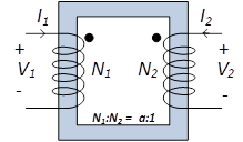
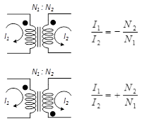
A current entering the dotted terminal of one coil produces voltage with a positive voltage reference at the dotted terminal of the second coil. |
|||
|
|
|
A current entering the dotted terminal of one coil produces voltage with a positive voltage reference at the dotted terminal of the second coil. |
|||
|
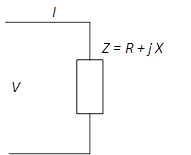
Voltages and currents in terms of phasors |
|
|
|||
|
Coefficient of mutual coupling |
|
|
|||
|
|
|
|
|||
|
|
|
Dot convention and current / voltage polarity reference |
|||
|
|
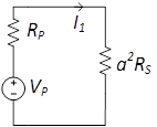
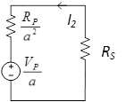
Reflection of secondary into primary
|
Reflection of primary into secondary
|
|||
|
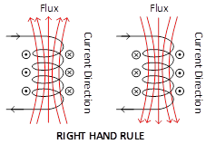
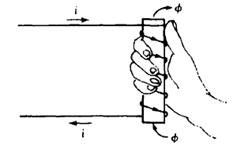
Current and flux direction using right hand rule |
|
|
|||
|
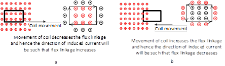
LENZ’S LAW
The direction of the induced voltage( in other words the current direction)will be such that it will oppose the change in the flux |
|
||||
|
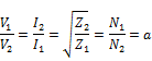
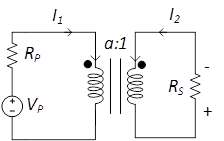
General Transformer Equation |
|
|
|||
|
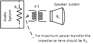
Impedance Matching |
|
If the transformer is acting as an impedance matching device than
|
|||
|
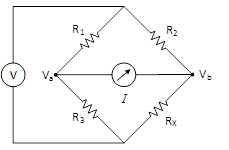
Bridge circuit can be used to determine the value of an unknown resistance.
|
The
bridge is balanced if
When the bridge is balanced then
|
|
|
|

|
|
|